AS/NZS reference
Electrical drawing symbols
Electrical components are also represented on floor plans using Australian Standard graphical symbols, set out in AS 1102.111:1997 (Graphical symbols for electrotechnology documentation, Part 111: architectural and topographical plans and diagrams). A sample of those 40 symbols is shown below. Search by name or browse by category.
Switch symbols show where each switch sits on the wall. The light or load it controls is usually tied back to it with a dashed switching line, so follow the line rather than assuming the nearest light. Two way switches come in pairs for stairs and long halls, with an intermediate switch between them when there are three or more control points. Mounting height is normally given in the drawing notes or legend, not on the symbol.
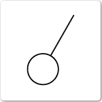
Switch, general 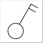
Switch, two pole 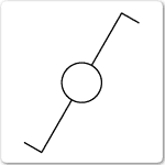
Switch, two way single pole 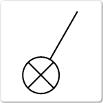
Switch with pilot light 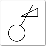
Switch with dimmer 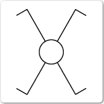
Switch, intermediate 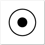
Switch, push button 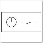
Time switch
Lighting symbols mark the outlet position on the ceiling or wall, not the exact fitting. The fitting itself usually comes from a luminaire schedule, keyed by a letter or number next to the symbol. Fluorescent symbols show the number of tubes, which tells you the fitting size when you rough in. Emergency and exit lighting is often drawn with its own symbols on a separate layer, so check the legend before you count fittings for a quote.
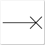
Lighting outlet, position 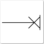
Lighting outlet on wall 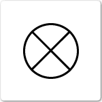
Lamp, general 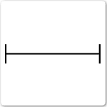
Fluorescent lamp, general 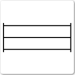
Fluorescent lamp, three tubes 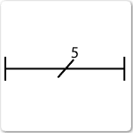
Fluorescent lamp, five tubes 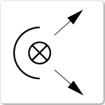
Flood light 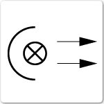
Spot light 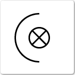
Projector, general
Socket outlet symbols show the number of outlets at each point and whether they are single or multiple. Dedicated circuits for appliances such as ovens, dishwashers or air conditioners are usually noted in text beside the symbol. Telecommunications outlets look similar to power outlets on some plans but are data cabling, which in Australia must be installed by a registered cabler.
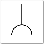
Socket outlet, power general 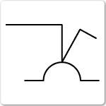
Socket outlet, single pole 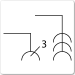
Multiple socket outlet, power 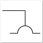
Socket outlet with shutter 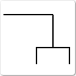
Socket outlet, telecommunications
These symbols mark the switchboard (distribution centre), the point where the supply enters the installation (the consumer's terminal), and junction or connection boxes. Plans rarely show every cable route; they show where things start and finish, and the electrician works out the run on site. Check the legend for whether a box is accessible, because junction boxes generally need to stay reachable.
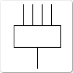
Distribution centre 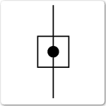
Consumer's terminal 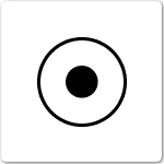
Connection or junction box 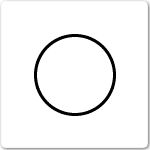
Box, general
System and tap-off outlets belong to a distributed signal system, typically TV antenna or MATV wiring in a building. A looped outlet passes the signal on to the next point, so the order of outlets on the plan matters. These are signal outlets, not power, though a power outlet is normally needed nearby for the equipment that plugs into them.
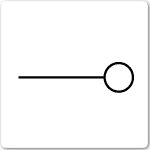
System outlet 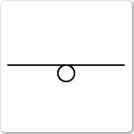
Looped system outlet 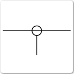
Subscriber's tap-off
Fixed appliances such as ceiling fans and water heaters get their own symbols because each needs its own supply arrangement. A water heater usually means a dedicated circuit, often on off-peak control, and a ceiling fan needs a fixing point and usually its own switch or controller. Check the drawing notes for the appliance rating so you can size the circuit.
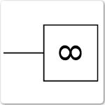
Fan 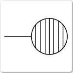
Water heater
Building symbols show the construction you are working in. Wall type tells you how cables can be run: a timber stud wall is easy to fish through, cavity brick and brick veneer need more planning. Door swings matter for switch placement, because switches belong on the latch side so they are reachable as the door opens.
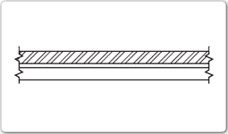
Wall, brick veneer 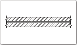
Wall, cavity brick 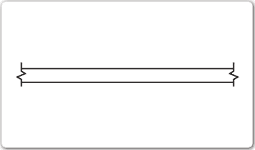
Wall, timber stud 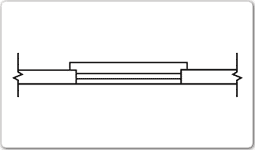
Window in single wall 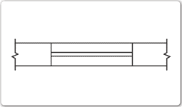
Window in cavity wall 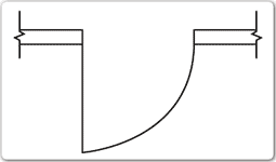
Door, swing single 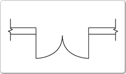
Door, swing double 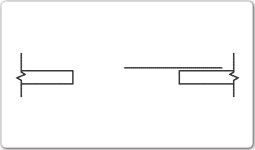
Door, sliding exposed 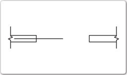
Door, sliding into pocket
Reading an electrical plan
- Start with the legend. Every drawing set should have one, and it overrides any general reference, including this page. Designers and drafting offices vary their symbols.
- Check the revision. Work from the latest issued revision and read the revision notes. Outlets get moved between revisions more often than anything else.
- Follow the switching lines. Dashed lines link each switch to what it controls. Count the lines, not the switches, when working out how many switched circuits a room needs.
- Read the notes for heights and circuits. Mounting heights, dedicated circuits and RCD arrangements are usually in the notes or a schedule, not on the symbol itself.
- Count from the plan, then walk the site. Take quantities off the plan for a quote, then check them on site. Plans show where things go, not how cables will actually run around the structure.
Once you have the points counted, the maximum demand calculator turns them into a supply size, and the cable sizing calculator sizes each circuit.
Symbols follow the conventions of AS 1102.111:1997 for electrotechnology documentation. Symbol style can vary between drafting offices and consultants. Always confirm against the legend on the specific drawing set you are working from.